I have found that peple can overclock their cfx's.
Ive got a fx 9750 G plus and i took it apart and found the 3 pin 4.3 mhz smd ceramic resonator.
My question is, can i use a non smd ceramic 3 pin ceramic resonator.
Does it have to be a smd in otherwords.
I also have a 2 pin 6mhz one, is it possibe to use a 2 pin instead of three, and iff so how is it hooked up?

 1 votes
Overclocking 9750
Started by
liquid
, Feb 26 2005 04:48 AM
28 replies to this topic
#1

liquid
-
- Members
-

- 66 posts
Wannabe Casio God
- Gender:Male
- Location:NZ
-
Calculators:
fx 9750 Plus
Posted 26 February 2005 - 04:48 AM
#2
huhn_m
-

- [Legends]
-
- 1957 posts
Casio Maniac
- Gender:Male
- Location:Germany / Dresden
-
Interests:Assembler(!!!)
Computers and Programming
Operating Systems
Programmable Calculators
Maths and everything arround it -
Calculators:
FX-82SX / AFX 2.0+ (ROM 1.03) / FX 1.0+ (ROM 1.03)
Posted 26 February 2005 - 04:58 PM
I think the overclocking was made by changing the quartz or sth. like that. I?m not too experienced at such detailed technics. But it should be possible.
Also welcome to the UCN!!
Also welcome to the UCN!!
#3
Guest_Guest_*
Guest_Guest_*
-

- Guests
Posted 26 February 2005 - 10:21 PM
Speaking of overclocking, does anyone know how to overclock a Casio CFX 9850GB+?
#4
liquid
-
- Members
-
- 66 posts
Wannabe Casio God
- Gender:Male
- Location:NZ
-
Calculators:
fx 9750 Plus
Posted 27 February 2005 - 08:49 PM
Speaking of overclocking, does anyone know how to overclock a Casio CFX 9850GB+?
Well that shoud be the same as trying to overclock my 9750 G plus(the layout might be a bit different though).
both of our calcs have the 4.3 Mhz resonator, and it would have to be replaced by one of a higher speed.
Open up ur calc and take a look if u want.
I just want to know if it matters if i replace the smd reonator wif a non smd one as these are much easier to obtain.
And can u use a 2 pin one (the one in the calc is three pin), and if so , how can it be hooked up.
Seems no one knows much about this on the UCF, but they do on the DCF, buts thats in german and translates badly.
Cmon, there must sumone else whos done this around here???!
#5
Marco
-

- Members
-
- 185 posts
Casio Freak
- Location:Dresden, Germany
-
Calculators:
Casio CFX 9850G (broken),
Casio CFX 9850GB,
Casio Algebra FX 2.0 Plus
Posted 27 February 2005 - 10:58 PM
As far as I know, SMD is just the shortcut for Surface Mounted Device and means nothing but the method how to get the thing onto the board (SMD devices are soldered directly onto it without pins or wires; you have blank areas with flat contacts)
So the resonator should work also if it's non SMD. (btw I looked up the thread in the DCF again and rockclimber reported on July 21th 04 that it "should be no problem to solder a non SMD resonator onto the board, too")
As for 2<->3 pin question, sorry, I really don't know sth about it. But I guess 2 pin will not work, the third one probably isn't just for fun However, you should ask Marcel, Matze or Rockclimber for that, they're the most skilled with it (you could call them the pioneers of CFX overclocking). But you'd better write them a mail as I haven't seen them on the DCF for a long time (and I'm sure they'll also understand it in English
  )
)
So the resonator should work also if it's non SMD. (btw I looked up the thread in the DCF again and rockclimber reported on July 21th 04 that it "should be no problem to solder a non SMD resonator onto the board, too")
As for 2<->3 pin question, sorry, I really don't know sth about it. But I guess 2 pin will not work, the third one probably isn't just for fun
However, you should ask Marcel, Matze or Rockclimber for that, they're the most skilled with it (you could call them the pioneers of CFX overclocking). But you'd better write them a mail as I haven't seen them on the DCF for a long time (and I'm sure they'll also understand it in English )
#6
liquid
-
- Members
-
- 66 posts
Wannabe Casio God
- Gender:Male
- Location:NZ
-
Calculators:
fx 9750 Plus
Posted 28 February 2005 - 02:21 AM
Thanks a lot Marco, i might as well spend a small amount on a 3 pin res to save me any trouble. When i try this(not now as i need my calc going for uni), prob in holidays i will post the results up here for non german speaking ppl to look up.
#7
Guest_Guest_*
Guest_Guest_*
-
- Guests
Posted 28 February 2005 - 04:09 PM
Can anyone provide a link to a site or provide a step-by-step tutorial to overclock a Casio CFX?
#8
Bob Vila
-

- Members
-
- 768 posts
Casio Overlord
- Gender:Male
- Location:USA
-
Calculators:
FX 1.0+ : CFX-9850 GB Plus : TI-81
Posted 28 February 2005 - 09:00 PM
try http://www.geocities.com/techfreak02/
edit--
eh, maybe not i guess this is only how to upgrade your memory
edit--
eh, maybe not
i guess this is only how to upgrade your memory
Edited by Bob Vila, 28 February 2005 - 09:04 PM.
#9
Marco
-
- Members
-
- 185 posts
Casio Freak
- Location:Dresden, Germany
-
Calculators:
Casio CFX 9850G (broken),
Casio CFX 9850GB,
Casio Algebra FX 2.0 Plus
Posted 28 February 2005 - 10:27 PM
A site about it doesn't exist, though around 10 people overclocked their calcs already Marcel never updated the techfreak site. It still gives a tutorial only how to upgrade RAM on the old black calc, while upgrading the new blue/white calcs is even much easier.Can anyone provide a link to a site or provide a step-by-step tutorial to overclock a Casio CFX?
OK so I'll give a short summary of the upgrading and overclocking Threads in the DCF made by Marcel, Matze, Rockclimber, Flori, Astrofreak, StarTrekMichi, foxtanz, Nukeduke, dr.jons and others:
Overclocking
Don't use a quartz pulse generator, it MUST be a resonator. Some tried it with a quartz but had problems with switching the calc on/off then; id didn't work really proper.
With resonators there have been no problems, and it also needn't to be an SMD. Frequencies tested successfully were 6MHz, 7.38MHz and 8MHz. 8.6MHz was also tested but didn't work anymore, seems this was to much for the calc. You can get SMD resonators at the most electronical handicraft shops for around 30 Cent.
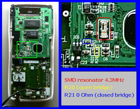
The procedure of overclocking now is relative easy. Open your calc and look for the original resonator @4.3MHz (there's only one inside. It has a metallcase, 6 pins that look like only three (but you have them at the left and the right side, thus 6) and it's bigger than the other SMD stuff. Next to it you have a label "X" or "X1". See picture below). Just unsolder it and solder the new resonator there. That's it, and it works the same for the old (black) and the new (blue white) calcs (The only thing that's a bit tricky is that it's SMD what you solder, look my above post what SMD means. But note, you also may use non SMD
).Overclocking your calc will make the batteries discharging quicker, but it's not reported how much quicker. Also overclocking brings another problem: calcs COM port runs at 9600 baud originally, but synchronised by that resonator. Replacing it with an 8MHz one for example will make the COM port running at 17860 baud, and the calc isn't able to communicate with other calcs or the PC anymore (also selecting baud rate on your PC manually will not work).
A solution was using two resonators, the original and a fast one, and make it selectable by a switch wich one you want to use. I don't know if anyone has done that yet.
Upgrading RAM on the new blue/white calcs
Some poeple requested for a tutorial how to upgrade the blue/white calc's RAM (for the old black ones this is described on the techfreak site already). Yesterday, rockclimber visited the DCF again and posted how to do this:
- open the calc
- look for the R20 and R21 resistor labels
- at R21, you have a resistor with 0 Ohm wich is nothing but a closed bridge
- R20 is left open (open bridge)
- unsolder the R21 resistor in order to make it an open bridge
- close the R20 bridge (you can do this either with the resistor from R21 or with a piece of wire).
That's it, your calc has 64KB now.
What I find very interesting is the way how rockclimber found out how to upgrade the RAM on these calcs - he just compared the board of the blue/white CFX9950GB Plus, wich is actual a CFX9850GB Plus with 32KB more RAM, with the board of this. The R20/21 resistors obviously have been the only difference.
Thus, each blue/white CFX9850GB Plus in fact HAS 64KB (that's another thing for the black calc where you have to build in a second RAM chip), but Casio disabled the upper 32 in order to have a reason making the CFX9950GB Plus more expensive
Actual I never thought of upgrading the RAM of my blue/white CFX9850GB Plus myself, but when I heared today it really should be THAT easy, I just couldn't resist and opened my calc some hours ago, willingly to make this RAM upgrade. Here's a picture of it:
But then courage left me and I wasn't brave enough to do it. I thought a CFX with 32KB mem is worth more than one with 64KB that doesn't work, so I coward closed my calc quickly.
And here is a picture made by Rockclimber: http://www.geocities...02/solder_4.jpg
#10
Guest_Guest_*
Guest_Guest_*
-
- Guests
Posted 28 February 2005 - 11:10 PM
Wow! You're really great Marco!
Thanks!!!!!!!!!!!!!!!!!!!!!!!!!!!!!!!!!!!!!!!!!!!!!!
Thanks!!!!!!!!!!!!!!!!!!!!!!!!!!!!!!!!!!!!!!!!!!!!!!
#11
liquid
-
- Members
-
- 66 posts
Wannabe Casio God
- Gender:Male
- Location:NZ
-
Calculators:
fx 9750 Plus
Posted 01 March 2005 - 05:26 AM
Marco, u should look at the part # on that ram chip, can u tell me if u can.
My blue + white 9750 has 32kBram and after looking up the sram chip on
http://www.hynix.com/eng
it was a 32KB chip, so i wont be able 2 upgrade my ram 2 64KB
Is your ram chip a hynix one or other brand, can u tell me becuase hynix only comes in 256Kbit and 1Mbit,,,,,but 64KB is 512Mbit ???
I cant see the part # on your picture its too low res
If u dont want to open your calc again i understand
#12
genesis
-

- Super Member
-
- 281 posts
UCF BASIC Programming Runner Up
- Location:Perth, Australia
- Interests:Speaking German, computers, defending CFX calculators...
-
Calculators:
CFX 9850 GB+
Posted 01 March 2005 - 08:57 AM
Wow, is it really that simple?  Wouldn't you be able to use the extra memory in exams? I'll probably leave my 9850 alone, after all, you shouldn't need to have 64 KB
  (and yes, I've already screwed up one of mine...)
Wouldn't you be able to use the extra memory in exams? I'll probably leave my 9850 alone, after all, you shouldn't need to have 64 KB (and yes, I've already screwed up one of mine...)
#13
Marco
-
- Members
-
- 185 posts
Casio Freak
- Location:Dresden, Germany
-
Calculators:
Casio CFX 9850G (broken),
Casio CFX 9850GB,
Casio Algebra FX 2.0 Plus
Posted 01 March 2005 - 09:49 AM
@guest: Thank Marcel, Matze, Rockclimber, ..., I just summarized what they found out.
@liquid: I screwed it up again, the SRAM was BS62LV1024SC-70 (BS62LV1024 series, manufacturer is BSI). The data sheet says:
70ns 20-35mA 2.4-5.5V very low power/voltage CMOS SRAM 128K x 8bit in 32-pin SOP package.
So it's even 128(!) KByte, not 64 only. Therefore I looked up the DCF's RAM thread again, Matze also said blue/white CFX 9850GB Plus/ 9950GB Plus use the same SRAM chip, and it's 128KByte. OS however can manage 64KB only.
So I wonder what's the reason. I think 128KB also would not make batteries discharging quicker, as the whole chip get's power anyways, just the upper address pins aren't connected (or is it possible to disable a RAM chip's power supply segmentwhise? Don't know). One possible reason might be if an 64KB SRAM also would not be cheaper than 128KB, and Casio didn't want to update the OS.
So it'll work this way for blue/white 9850 only, not for your 9750, sorry (nobody upgraded a 9750 yet). Maybe you could upgrade RAM similar to the black calc where you also need a second RAM chip, but that'll be more complicated. If you'd like to try it, you should ask Matze or rockclimber. Maybe they can tell you how to do.
@liquid: I screwed it up again, the SRAM was BS62LV1024SC-70 (BS62LV1024 series, manufacturer is BSI). The data sheet says:
70ns 20-35mA 2.4-5.5V very low power/voltage CMOS SRAM 128K x 8bit in 32-pin SOP package.
So it's even 128(!) KByte, not 64 only. Therefore I looked up the DCF's RAM thread again, Matze also said blue/white CFX 9850GB Plus/ 9950GB Plus use the same SRAM chip, and it's 128KByte. OS however can manage 64KB only.
So I wonder what's the reason. I think 128KB also would not make batteries discharging quicker, as the whole chip get's power anyways, just the upper address pins aren't connected (or is it possible to disable a RAM chip's power supply segmentwhise? Don't know). One possible reason might be if an 64KB SRAM also would not be cheaper than 128KB, and Casio didn't want to update the OS.
So it'll work this way for blue/white 9850 only, not for your 9750, sorry
(nobody upgraded a 9750 yet). Maybe you could upgrade RAM similar to the black calc where you also need a second RAM chip, but that'll be more complicated. If you'd like to try it, you should ask Matze or rockclimber. Maybe they can tell you how to do.
#14
Guest_Guest_*
Guest_Guest_*
-
- Guests
Posted 01 March 2005 - 04:59 PM
For overclocking your CFX, which 8Mhz resonator would you recommened?
#15
Guest_Guest_*
Guest_Guest_*
-
- Guests
Posted 05 March 2005 - 03:57 PM
the calculator memory upgrade works - just tried it
#16
PerCasioAdAstra
-

- Members
-
- 83 posts
Casio Addict
- Location:Stavanger, Norway
- Interests:Programming, gaming, gf, ..
-
Calculators:
CFX 9850 GB PLUS WE;
Posted 06 March 2005 - 12:32 PM
this looks neat. Better try this, as soon as my exams are over 
#17
R00KIE
-

- Members
-
- 155 posts
Casio Freak
- Location:Portugal
- Interests:Electronics, games, programming
-
Calculators:
HP49G ROM 1.24; CASIO CFX-9850GB PLUS;CASIO FX-6300G; CASIO FX-82TL
Posted 07 March 2005 - 10:33 AM
Don't forget that overclocking drains the batteries faster !
#18
Guest_Guest_*
Guest_Guest_*
-
- Guests
Posted 18 March 2005 - 12:44 AM
Speaking of overclocking and modding up calcs
Has any one ever been known to hack into/modify the os on a casio??
It would be really cool if i could change the os
btw, i own a cfx 9850 gb+
Has any one ever been known to hack into/modify the os on a casio??
It would be really cool if i could change the os
btw, i own a cfx 9850 gb+
#19
Guest_Liquid(not logged in)_*
Guest_Liquid(not logged in)_*
-
- Guests
Posted 19 March 2005 - 10:05 PM
Has any one ever been known to hack into/modify the os on a casio??
It would be really cool if i could change the os
Yes someone has, his webstie is:
http://www.rkk.cz/~mpoupe/
Unless u want to unsolder your rom chip, read the rom, change it, then resolder the new rom back in the u cant change thr OS.
#20
Guest_Guest_Matze_*_*
Guest_Guest_Matze_*_*
-
- Guests
Posted 28 October 2005 - 01:13 AM
Hello there
Here am I, the one already mentioned in this thread. I was just sitting around, asking how it would be to begn modding my CFX again:)
History:
I lost my modded one a few months ago, got an exchange one from a friend. But this has to be modded, too)))
Just to sum up:
I only had success with a 6MHz Quartz in my previous calculator, but I made a lot of crap with it (cut some "Leiterbahnen???"oehm, cut some of these copperthings to the resonator, where it is connected to the cpu, sry don't know the word.)
But I will try 8MHz Resonator from Conrad Electronics, I bought last year for my old calculator.
To Memoryupgrade:
Yes, it is a 128kbyte SRam.
And... yes, only maximum 64kbyte are accessible by CPU.
BUT: The Adressline for the upper 64kbyte is connected, too! But impossible to follow this connection on PCB.
I disconnected it (there is a 0 Ohm Resistor next to SRAM), connected a resistor of 200k to Vcc and a Jumper to GND, so i could switch between 2 banks of 64kbyte (But do this only when calc. is off, else u need to reset memory^^) Advantages: With softwarereset only the selected memory bank is cleared, because the reset just overwrites everything. So the upper 64kbyte are not accessible -> not cleared.
I already wrote a tutorial about this: http://www.eow.ath.cx/other/casio
Ah i see, due to domain changing, this wasn't accessible anymore.
And... I want to thank you You can't imagine the smile on my face when I read my name here! It's great that you know me )
But the real Idea came from Marcus, owner of techfreak site. He told me evrything and I just had a closer look to it.
So, I'll sleep now. In germany it is 3 'o clock in the morning, am? or pm? sry i cannot remember what u say ^^ but it is 3 hours after midnight right now.
see ya, freaks
Here am I, the one already mentioned in this thread. I was just sitting around, asking how it would be to begn modding my CFX again:)
History:
I lost my modded one a few months ago, got an exchange one from a friend. But this has to be modded, too
)))Just to sum up:
I only had success with a 6MHz Quartz in my previous calculator, but I made a lot of crap with it (cut some "Leiterbahnen???"oehm, cut some of these copperthings to the resonator, where it is connected to the cpu, sry don't know the word.)
But I will try 8MHz Resonator from Conrad Electronics, I bought last year for my old calculator.
To Memoryupgrade:
Yes, it is a 128kbyte SRam.
And... yes, only maximum 64kbyte are accessible by CPU.
BUT: The Adressline for the upper 64kbyte is connected, too! But impossible to follow this connection on PCB.
I disconnected it (there is a 0 Ohm Resistor next to SRAM), connected a resistor of 200k to Vcc and a Jumper to GND, so i could switch between 2 banks of 64kbyte (But do this only when calc. is off, else u need to reset memory^^) Advantages: With softwarereset only the selected memory bank is cleared, because the reset just overwrites everything. So the upper 64kbyte are not accessible -> not cleared.
I already wrote a tutorial about this: http://www.eow.ath.cx/other/casio
Ah i see, due to domain changing, this wasn't accessible anymore.
And... I want to thank you
You can't imagine the smile on my face when I read my name here! It's great that you know me )But the real Idea came from Marcus, owner of techfreak site. He told me evrything and I just had a closer look to it.
So, I'll sleep now. In germany it is 3 'o clock in the morning, am? or pm? sry i cannot remember what u say ^^ but it is 3 hours after midnight right now.
see ya, freaks
#21
Guest_Guest_Matze_*_*
Guest_Guest_Matze_*_*
-
- Guests
Posted 28 October 2005 - 11:38 AM
Okay here am I again...
I just tried to install 8MHz ceramic resonator. 2pin or 3 pin doesn't matter (to answer entry post). Just don't connect GND (middle Pin), when using 2 pin resonator.
I have massive graphic errors... Menu will always show good, but I can't do anything without errors.
I will try 7,3MHz Quartz, because I don't have any other resonators (but resonator should work better than quartz!)
All what I've found out is that the display itself can't handle the high clock. The display power supply (usually 18V) falls down to 11-12V because the switching power supply can't handle this "high" load. Sometimes, the calc draws up to 30mA from power supply. Maybe it is just the CPU itself that doesn't do this high clock.
But RAM and ROM definitively are in specs. (RAM: 70ns -> 14MHz, ROM 30ns -> a lot more MHz )
In normal operation, it draws 6mA when calculating, 2-4 when idle. at 6MHz, my old one drew 8mA when calculating, 2-4 when idle. The CPU seems to have "idle" mechanisms like todays computer processors have
To ram modification:
Normally, the "128kbyte" adress pin is connected to GND. But there is a possibility to connect it to CPU. But this doesn't have any effect (I will try with second jumper, later)
Thing is: CPU is 16bit.
16bit allows to adress 65535byte _> 64kbyte.
I don't have any hope to bring the calc to 128kbyte of memory.
And: I think I won't overclock mine as it will be impossible to connect it to pc then. I doesn't have enough time to develop the baudrate converter and even if i do: Nearly noone will be able to build it!
There will be an AVR microcontroller that has to be programmed. and a battery. and this small MAX232 you know from the link cable. And maybe we need external RAM to store the WHOLE communication first (microcontroller pretends to be calculator, loads the hole program, then it pretends to be PC and transfers to calculator) because I don't know the allowed waittimes in transmission protocol (but I will try it out, maybe next year^^)
A thing I ever wanted to do is multiplayer gaming with microcontroller between 2 calcs because then it would be possible to transfer data from one calc 2 the other IN PROGRAMS. but... don't have big hopes. transmission speed will be very low... maybe calc will even show "transmission complete" screen after that... would not be good
So, I'll continue my work with overclocking now.
bye,
Matze
I just tried to install 8MHz ceramic resonator. 2pin or 3 pin doesn't matter (to answer entry post). Just don't connect GND (middle Pin), when using 2 pin resonator.
I have massive graphic errors... Menu will always show good, but I can't do anything without errors.
I will try 7,3MHz Quartz, because I don't have any other resonators (but resonator should work better than quartz!)
All what I've found out is that the display itself can't handle the high clock. The display power supply (usually 18V) falls down to 11-12V because the switching power supply can't handle this "high" load. Sometimes, the calc draws up to 30mA from power supply. Maybe it is just the CPU itself that doesn't do this high clock.
But RAM and ROM definitively are in specs. (RAM: 70ns -> 14MHz, ROM 30ns -> a lot more MHz
)In normal operation, it draws 6mA when calculating, 2-4 when idle. at 6MHz, my old one drew 8mA when calculating, 2-4 when idle. The CPU seems to have "idle" mechanisms like todays computer processors have
To ram modification:
Normally, the "128kbyte" adress pin is connected to GND. But there is a possibility to connect it to CPU. But this doesn't have any effect (I will try with second jumper, later)
Thing is: CPU is 16bit.
16bit allows to adress 65535byte _> 64kbyte.
I don't have any hope to bring the calc to 128kbyte of memory.
And: I think I won't overclock mine as it will be impossible to connect it to pc then. I doesn't have enough time to develop the baudrate converter and even if i do: Nearly noone will be able to build it!
There will be an AVR microcontroller that has to be programmed. and a battery. and this small MAX232 you know from the link cable. And maybe we need external RAM to store the WHOLE communication first (microcontroller pretends to be calculator, loads the hole program, then it pretends to be PC and transfers to calculator) because I don't know the allowed waittimes in transmission protocol (but I will try it out, maybe next year^^)
A thing I ever wanted to do is multiplayer gaming with microcontroller between 2 calcs because then it would be possible to transfer data from one calc 2 the other IN PROGRAMS. but... don't have big hopes. transmission speed will be very low... maybe calc will even show "transmission complete" screen after that... would not be good
So, I'll continue my work with overclocking now.
bye,
Matze
#22
Guest_Guest_Matze_*_*
Guest_Guest_Matze_*_*
-
- Guests
Posted 28 October 2005 - 12:05 PM
uhh i'm discovering a VERY NEW THING )))))))))))
The second switch on PCB is for language change.
library is there in french, too))
photos will follow... sry, digicam is stolen -> only webcam pix
)))))))))))The second switch on PCB is for language change.
library is there in french, too
))photos will follow... sry, digicam is stolen -> only webcam pix
#23
Guest_Guest_Matze_*_*
Guest_Guest_Matze_*_*
-
- Guests
Posted 28 October 2005 - 01:06 PM
Okay, research finished
So... Second Switch changes only language of program library. My calculator has GERMAN as standard and FRENCH as second.
Standard, R22 is closed, and... R23? (dunno, calculator closed already...) open.
Second: R22 open, R23 closed.
What is your standard language for the non-german calculators? I can't imagine that all of you have a german library...
Maybe there are TWO versions of Hardware:
CFX 9x50GB Plus English/chinese?
CFX 9x50GB Plus German/French
because 9850 and 9950 are the same (memory switch)
and 2 languages... (language switch)
so they just have to produce ONE calculator. Half of them get flashed the english/chinese ROM, the other half german/french.
THE VERY LAST THING to discover in hardware is the R18/R19 switch (sry i can't read it on my picture, i mean the one above ram, u have to remove when wiring a 2x64kbyte switch)
Because normally, it is connected to GND and optionally to CPU.
Okay and now comes the clue... the pin of the cpu u can connect to this adress pin of the ram IS CONNECTED TO SOMEWHERE ELSE. the connection goes down to the bottom side of the pcb... I don't know where it goes Maybe to ROM. rom has 8Mbit -> 1 mbyte(1024kbyte). or 16 * 64kbyte blocks (unsure!).
now my assumption: there is a small switch anywhere in the software to enable this crappy other 64kbyte. maybe it is just a switch like my external hardware one but in software. BUT IT MUST BE POSSIBLE TO ENABLE THE SECOND 64KBYTE. casio MUST have thought at us poor pupils wanting to cheat in tests...
fuck we need to analyze the whole rom.
I swear i will do it as far as i can. I DO IT. maybe in a few years but this has to be done *g*
I'm going to consider martin's site for disassembling, maybe they haven't changed the op codes
bye,
Matze
So... Second Switch changes only language of program library. My calculator has GERMAN as standard and FRENCH as second.
Standard, R22 is closed, and... R23? (dunno, calculator closed already...) open.
Second: R22 open, R23 closed.
What is your standard language for the non-german calculators? I can't imagine that all of you have a german library...
Maybe there are TWO versions of Hardware:
CFX 9x50GB Plus English/chinese?
CFX 9x50GB Plus German/French
because 9850 and 9950 are the same (memory switch)
and 2 languages... (language switch)
so they just have to produce ONE calculator. Half of them get flashed the english/chinese ROM, the other half german/french.
THE VERY LAST THING to discover in hardware is the R18/R19 switch (sry i can't read it on my picture, i mean the one above ram, u have to remove when wiring a 2x64kbyte switch)
Because normally, it is connected to GND and optionally to CPU.
Okay and now comes the clue... the pin of the cpu u can connect to this adress pin of the ram IS CONNECTED TO SOMEWHERE ELSE. the connection goes down to the bottom side of the pcb... I don't know where it goes
Maybe to ROM. rom has 8Mbit -> 1 mbyte(1024kbyte). or 16 * 64kbyte blocks (unsure!).now my assumption: there is a small switch anywhere in the software to enable this crappy other 64kbyte. maybe it is just a switch like my external hardware one but in software. BUT IT MUST BE POSSIBLE TO ENABLE THE SECOND 64KBYTE. casio MUST have thought at us poor pupils wanting to cheat in tests...
fuck we need to analyze the whole rom.
I swear i will do it as far as i can. I DO IT. maybe in a few years but this has to be done *g*
I'm going to consider martin's site for disassembling, maybe they haven't changed the op codes
bye,
Matze
#24
liquid
-
- Members
-
- 66 posts
Wannabe Casio God
- Gender:Male
- Location:NZ
-
Calculators:
fx 9750 Plus
Posted 02 November 2005 - 09:03 AM
Excellent work!
Great to know there are still some people hacking this calc lol
Thanks for the advice on the 2 pin resonator, u see i got a 2 pin 6 Mhz one from a broken mouse, might try it out.
Maby once i get into elec engr i will rom read my calc and continue the legace, but probably not lol,
bye
Great to know there are still some people hacking this calc lol
Thanks for the advice on the 2 pin resonator, u see i got a 2 pin 6 Mhz one from a broken mouse, might try it out.
Maby once i get into elec engr i will rom read my calc and continue the legace, but probably not lol,
bye
#25
Guest_Guest_Matze_*_*
Guest_Guest_Matze_*_*
-
- Guests
Posted 06 November 2005 - 05:05 PM
kk
Well but i thought about my ideas.. it's just not worth anything trying to hack this calc more ^^
the languageswitch is not needed by anyone. Rom read wont be easy, dissassembling maybe impossible.
bye
Matze
Well but i thought about my ideas.. it's just not worth anything trying to hack this calc more ^^
the languageswitch is not needed by anyone. Rom read wont be easy, dissassembling maybe impossible.
bye
Matze
#26
Guest_Da mr Jackal_*
Guest_Da mr Jackal_*
-
- Guests
Posted 04 May 2006 - 03:55 PM
 Memory mod works very well, it's just a little tricky. The parts are very small to handle and especially to solder. To close the R20 bridge, don't use a piece of wire. It's just 2 hard. Just use soldering tin.
#27
Guest_Da mr Jackal_*
Guest_Da mr Jackal_*
-
- Guests
Posted 21 September 2006 - 01:32 PM
Let's kick this forum again then 
Why would you have to make a baudrate converter to connect an oc'ed casio? You can just adjust the baudrate manually in "Device Manager"?
Why would you have to make a baudrate converter to connect an oc'ed casio? You can just adjust the baudrate manually in "Device Manager"?
#28
Guest_Bradley_*
Guest_Bradley_*
-
- Guests
Posted 14 April 2008 - 05:40 AM
Thats a good question and sorry but I don't know how to do that but you know what would be really cool is to have a up graded Casio CFX-9850GB PLUS so it's like a (Gaming Calculator).I have found that peple can overclock their cfx's.
Ive got a fx 9750 G plus and i took it apart and found the 3 pin 4.3 mhz smd ceramic resonator.
My question is, can i use a non smd ceramic 3 pin ceramic resonator.
Does it have to be a smd in otherwords.
I also have a 2 pin 6mhz one, is it possibe to use a 2 pin instead of three, and iff so how is it hooked up?
Be good to have some 3D games to play with during those boring maths lessions. Imagine having real, proper games that run at a decent speed on a calculator!
#29
demolitionb
-

- Members
-
- 1 posts
Newbie
Posted 25 August 2008 - 02:37 PM
thx to this thread, it helps me to overclock my cfx 9850g to 8 MHz....
But I miss some Tutorials in the www, so i wrote my own one on my Blog with some Pictures... klick me .... hm, the link funktion does not work, so see there:
http://einfachnurbe....erclocking.html
Only one, I'm a german guy and the tutorial is in german too....
And when somebody like my Blog he can get the feed
1 user(s) are reading this topic
0 members, 1 guests, 0 anonymous users

