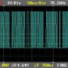
it looks like that the using power of that interface is around 0.5v - 0.7v as a high signal,
so my cheap Oscilloscopes told me that... 
Dear Reiner Vogt,
The 0.5v-0.7v level is not sufficient for noise immunity, I guess the measurement was inaccurate.
Please try the followings,
1. mark your 3-wires (photo supplied in the first post); Tx, Rx and GND.
2. On the 2.5mm stereo jack, tip=Tx, middle=Rx, base=GND, your marking should confirm with it.
3. Connect the 2.5mm stereo jack to the calculator and the wires marked GND to the oscilloscope ground and Tx to the measuring terminal of the oscilloscope.
4. Put the calculator in the transmitting (send) mode, pretending to send data.
5. Observe the signal on the oscilloscope; it should be a square wave of some amplitude. Measure the amplitude of the signal. You may need to adjust the scale and the time base of the oscilloscope to get a correct reading.
Unfortunately, I couldn?t get access to any data concerning the fx-5800p.
Regards.


 :
: 


