Jump to content


Photo
- - - - -

A Chance To Save All Data From Fx5800p To Pc?


  • Please log in to reply
15 replies to this topic

#1 Reiner Vogt

Reiner Vogt

    Newbie

  • Members
  • Pip
  • 7 posts
  • Gender:Male
  • Location:Germany, Earth... :-)
  • Interests:Cinema, computer, electronic development based on Risc CPU's like Microchip PIC16/28, bicycling

  • Calculators:
    On the search after ...

Posted 08 July 2008 - 04:05 PM

Hi all,

i am looking for a possibility to save fx5800p programm/fmla data into a pc
or an alternate storage medium. :banghead:

Does the interface which one be supposed to work only in the mode from the same
calculator to calculator (fx5800p), is this usable also differently - for example e.g.
into another processor like Microship PIC oder ATMEL-CPU, or a ser. Port from or
to a PC? :rolleyes:

A little screenshot :plol: :

Posted Image

Has anybody an idear or know a wiring diagram of that fx5800p interface port?

regards,
Reiner V.

#2 ECE

ECE

    Casio Freak

  • Members
  • PipPipPipPip
  • 152 posts
  • Gender:Not Telling
  • Location:USA

  • Calculators:
    ClassPad300 Plus o.s3.06.1000
    fx-CG20 o.s1.04
    fx9860GII SD o.s2.00
    fx9860G Slim o.s1.10
    fx9860GSD o.s2.01 (GII hacked)
    Algebra FX2.0 Plus
    CFX9850GBplus
    fx5800p
    fx3650p
    fx570ES Plus
    EA-200 Casio Data Analyzer

Posted 08 July 2008 - 07:39 PM

Hi Reiner Vogt,
I?m not sure I?ve understand you well; in the title of the post you wrote ?Interface from 1.5v to 5v. TTL?.
Are you saying that the communication signal level of the fx-5800p is 1.5v? Did you measure it or read it from a specification document?
If so, then you need a level converter, which is simple to design and build, also you need a s/w interface for the PC. I can help with the h/w if I can get enough information about the output signal.

#3 Reiner Vogt

Reiner Vogt

    Newbie

  • Members
  • Pip
  • 7 posts
  • Gender:Male
  • Location:Germany, Earth... :-)
  • Interests:Cinema, computer, electronic development based on Risc CPU's like Microchip PIC16/28, bicycling

  • Calculators:
    On the search after ...

Posted 08 July 2008 - 08:41 PM

I?m not sure I?ve understand you well; in the title of the post you wrote ?Interface from 1.5v to 5v. TTL?.
Are you saying that the communication signal level of the fx-5800p is 1.5v?


Hi M.Yasser,

so I believe that the voltage level of the interface is 1.5v - because the
battery power of the fx5800p is only equipped with 1 pieces of AAA (LR03). :roflol:

i'm sorry i havn't a specification document of my calculator, do you have it? it will
be help me by the development of an little interface... :rolleyes:

On the manufacturer site i havn't found anything specification document about
the casio fx5800p calculator. :blink:

I can help with the h/w if I can get enough information about the output signal.


It will be fine when you can help me with that level-interface. I want to measuring
the voltage on the 3-wire (i guess it is a serial communication) - when i got an
result i will post it here... :rock:

so long,
Reiner V.

#4 Reiner Vogt

Reiner Vogt

    Newbie

  • Members
  • Pip
  • 7 posts
  • Gender:Male
  • Location:Germany, Earth... :-)
  • Interests:Cinema, computer, electronic development based on Risc CPU's like Microchip PIC16/28, bicycling

  • Calculators:
    On the search after ...

Posted 08 July 2008 - 09:09 PM

Hi M.Yasser,

it looks like that the using power of that interface is around 0.5v - 0.7v as a high signal,
so my cheap Oscilloscopes told me that... :roflol:

Knows anyone some data sheet about the fx-5800p communication interface? :nonono:

so long,
Reiner V.

#5 ECE

ECE

    Casio Freak

  • Members
  • PipPipPipPip
  • 152 posts
  • Gender:Not Telling
  • Location:USA

  • Calculators:
    ClassPad300 Plus o.s3.06.1000
    fx-CG20 o.s1.04
    fx9860GII SD o.s2.00
    fx9860G Slim o.s1.10
    fx9860GSD o.s2.01 (GII hacked)
    Algebra FX2.0 Plus
    CFX9850GBplus
    fx5800p
    fx3650p
    fx570ES Plus
    EA-200 Casio Data Analyzer

Posted 09 July 2008 - 11:56 AM

it looks like that the using power of that interface is around 0.5v - 0.7v as a high signal,
so my cheap Oscilloscopes told me that... :roflol:


Dear Reiner Vogt,

The 0.5v-0.7v level is not sufficient for noise immunity, I guess the measurement was inaccurate.

Please try the followings,

1. mark your 3-wires (photo supplied in the first post); Tx, Rx and GND.

2. On the 2.5mm stereo jack, tip=Tx, middle=Rx, base=GND, your marking should confirm with it.

3. Connect the 2.5mm stereo jack to the calculator and the wires marked GND to the oscilloscope ground and Tx to the measuring terminal of the oscilloscope.

4. Put the calculator in the transmitting (send) mode, pretending to send data.

5. Observe the signal on the oscilloscope; it should be a square wave of some amplitude. Measure the amplitude of the signal. You may need to adjust the scale and the time base of the oscilloscope to get a correct reading.

Unfortunately, I couldn?t get access to any data concerning the fx-5800p.

Regards.

#6 Reiner Vogt

Reiner Vogt

    Newbie

  • Members
  • Pip
  • 7 posts
  • Gender:Male
  • Location:Germany, Earth... :-)
  • Interests:Cinema, computer, electronic development based on Risc CPU's like Microchip PIC16/28, bicycling

  • Calculators:
    On the search after ...

Posted 09 July 2008 - 12:27 PM

...Observe the signal on the oscilloscope; it should be a square wave of some amplitude. Measure the
amplitude of the signal. You may need to adjust the scale and the time base of the oscilloscope to get a
correct reading.


I'm sorry, nothing to see - one signal goes from high to low, the other one from
low to high...and than the calculator say: transmission timeout (or euqal in receiving mode). :unsure:

Unfortunately, I couldn?t get access to any data concerning the fx-5800p.


Thats also my problem - no information available... :profanity:

#7 ECE

ECE

    Casio Freak

  • Members
  • PipPipPipPip
  • 152 posts
  • Gender:Not Telling
  • Location:USA

  • Calculators:
    ClassPad300 Plus o.s3.06.1000
    fx-CG20 o.s1.04
    fx9860GII SD o.s2.00
    fx9860G Slim o.s1.10
    fx9860GSD o.s2.01 (GII hacked)
    Algebra FX2.0 Plus
    CFX9850GBplus
    fx5800p
    fx3650p
    fx570ES Plus
    EA-200 Casio Data Analyzer

Posted 09 July 2008 - 12:43 PM

I'm sorry, nothing to see - one signal goes from high to low, the other one from
low to high...and than the calculator say: transmission timeout (or euqal in receiving mode). :unsure:


Yes, this is the hand shaking signal. The calc. is waiting for response from the receiving Rx, so you must emulate an acknowledge signal. I don?t know the level of that signal. I?ll try some search about it. I?ll post if I found something useful, you may try to put the calc. in the receive mode and measure the Rx signal to find out.

#8 Reiner Vogt

Reiner Vogt

    Newbie

  • Members
  • Pip
  • 7 posts
  • Gender:Male
  • Location:Germany, Earth... :-)
  • Interests:Cinema, computer, electronic development based on Risc CPU's like Microchip PIC16/28, bicycling

  • Calculators:
    On the search after ...

Posted 09 July 2008 - 01:15 PM

Yes, this is the hand shaking signal. The calc. is waiting for response from the receiving Rx,
so you must emulate an acknowledge signal. I don’t know the level of that signal.


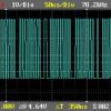
Hier are a overlayed picture of the oscilloscope mesurement:

Posted Image

The volts/div is set to 50mV.

so long,
Reiner V.

#9 Reiner Vogt

Reiner Vogt

    Newbie

  • Members
  • Pip
  • 7 posts
  • Gender:Male
  • Location:Germany, Earth... :-)
  • Interests:Cinema, computer, electronic development based on Risc CPU's like Microchip PIC16/28, bicycling

  • Calculators:
    On the search after ...

Posted 12 July 2008 - 08:05 PM

Hi all,

in consideration of non existing or available techn. Information about the fx-5800p
i have stop now my personal project in fact of too little chances to reach the target.

Thanks to everyone who wants to help me...

so long,
Reiner V.

#10 ECE

ECE

    Casio Freak

  • Members
  • PipPipPipPip
  • 152 posts
  • Gender:Not Telling
  • Location:USA

  • Calculators:
    ClassPad300 Plus o.s3.06.1000
    fx-CG20 o.s1.04
    fx9860GII SD o.s2.00
    fx9860G Slim o.s1.10
    fx9860GSD o.s2.01 (GII hacked)
    Algebra FX2.0 Plus
    CFX9850GBplus
    fx5800p
    fx3650p
    fx570ES Plus
    EA-200 Casio Data Analyzer

Posted 13 July 2008 - 12:42 PM

Dear Reiner Vogt,
Iam sorry you are disappointed, let us give it another try; have you set your oscilloscope to DC voltage-> The amplitude (0.025v.) is very small!!
I still think that a small modification to http://www.stormbase.net/images/56.png will work for you.
Please don’t quit easily.

#11 Reiner Vogt

Reiner Vogt

    Newbie

  • Members
  • Pip
  • 7 posts
  • Gender:Male
  • Location:Germany, Earth... :-)
  • Interests:Cinema, computer, electronic development based on Risc CPU's like Microchip PIC16/28, bicycling

  • Calculators:
    On the search after ...

Posted 21 July 2008 - 11:16 PM

Please don’t quit easily.

Hi M.Yasser,

thanks a lot for your great idears and help to my little "like to have" project. Today,
i have sold my fx-5800p calculator - Still have been able to obtain a very good price... :banghead:

I think I want to buy another pocket calculator for me in the next time. I don't know
which model, perhaps "Casio FX-9860 G SD" yet - Would this be the right choice -> :roflol:

#12 ECE

ECE

    Casio Freak

  • Members
  • PipPipPipPip
  • 152 posts
  • Gender:Not Telling
  • Location:USA

  • Calculators:
    ClassPad300 Plus o.s3.06.1000
    fx-CG20 o.s1.04
    fx9860GII SD o.s2.00
    fx9860G Slim o.s1.10
    fx9860GSD o.s2.01 (GII hacked)
    Algebra FX2.0 Plus
    CFX9850GBplus
    fx5800p
    fx3650p
    fx570ES Plus
    EA-200 Casio Data Analyzer

Posted 22 July 2008 - 08:21 AM

Yes, I think its a great choice.
Good Luck. :)

#13 kucalc

kucalc

    Casio Maniac

  • [Legends]
  • PipPipPipPipPipPipPipPip
  • 1422 posts
  • Gender:Male
  • Location:USA
  • Interests:Programming: C/C++, Fortran, LISP, COBOL 85 Standard, PHP, x86 and SH3 Assembly

    Computer graphics

  • Calculators:
    fx-9860G / fx-7400G Plus / Algebra FX 2.0+ / fx-9770G / CFX-9850G / CFX-9850GB+ / TI-89 / TI-nSpire

Posted 24 July 2008 - 02:17 AM

Well it depends on what you are going to use it for. Other good looking alternatives are HP-200LX, ClassPad, etc.

#14 Guest_Michael Chu_*

Guest_Michael Chu_*
  • Guests

Posted 27 December 2008 - 03:03 PM

Dear Reiner Vogt,
Iam sorry you are disappointed, let us give it another try; have you set your oscilloscope to DC voltage-> The amplitude (0.025v.) is very small!!
I still think that a small modification to http://www.stormbase.net/images/56.png will work for you.
Please don’t quit easily.


Hi Yasser,

I am trying the project to download program from 5800P to PC by RS232. At PC side, I understand the use of MAX232. But at 5800P side, I found the operate voltage is at 0 to 2.5V. I would like to know any interface to suit the mentioned voltage level. As pirmary checking of pulse signal on data lines of 5800P, a simple RS232 interface is not enough because it seems not use self clocking. Therefore, a modification of circuit in 56.png should be carry out.

#15 ECE

ECE

    Casio Freak

  • Members
  • PipPipPipPip
  • 152 posts
  • Gender:Not Telling
  • Location:USA

  • Calculators:
    ClassPad300 Plus o.s3.06.1000
    fx-CG20 o.s1.04
    fx9860GII SD o.s2.00
    fx9860G Slim o.s1.10
    fx9860GSD o.s2.01 (GII hacked)
    Algebra FX2.0 Plus
    CFX9850GBplus
    fx5800p
    fx3650p
    fx570ES Plus
    EA-200 Casio Data Analyzer

Posted 27 December 2008 - 09:50 PM

Hi,
If the signal is oscillating between 0v. and 2.5v.,then I assume that it is half the TTL voltage level. Thus a simple level converter may be implemented using a comparator for the transmit part of the signal and a clipping circuit; may be implemented using a zener diode for the receiving part of the signal.
The MAX232c accepts (0-0.8)v. as logic zero and (2-5)v. as logic one. Between 0.8 v.and 2v. is undefined.
As a first trial, put a reference voltage of 0.4 or 0.5 to the –ve terminal of the comparator and solder the transmitted (Tx) signal to the +ve terminal of the copmp. Supply the comp. from the same 5v. regulator of the circuit. The o/p of this circuit will be 5v. for each i/p greater than 0.5v and 0v. otherwise.
For the receiving signal, a zener diode of 2.5v. may be used to clip the logic one (5v.) to 2.5v.
From here you may start your experiments , adjusting the reference voltage of the comp. and the clipping zener until you have a stable readings.
Another helpful thing to do is to havet two units, connect them with SB-62 cable and attach the probes of the oscilloscope to the Tx,Rx,GND wires. Observe the levels of the Tx,Rx with respect to GND.

#16 Guest_Bulent_*

Guest_Bulent_*
  • Guests

Posted 04 July 2011 - 08:53 AM

Electronic interface no problem but how we learn the protocol of fx5800p?


1 user(s) are reading this topic

0 members, 1 guests, 0 anonymous users