


I picked a Casio CFX-9850GB+ up from an op shop a few months ago, and while I certainly don't see myself fully exploiting its mathematical capabilities anytime soon (understatement of the year) it's proven a lot of fun trying to create useable programs (read: games
 ) for its (imo poorly optimised...) BASIC interpreter. (Figuring out "1->A" without an instruction manual and no internet (at the time) was a lot of fun though...
  )
)A little more recently I found a TI-83+ (the blue kind
 ) hiding in a corner in an odds-and-ends recycle/disposal warehouse and after getting it working (the (-) battery pad was all but completely corroded away
  - it must have been hiding for a long time!) and poking around the UI a bit I promptly concluded I'd gotten a little too used to my Casio and would need to do some (re-)learning. For some incentive, my next step was to look around and see what I could do with it (ie, what others had done with it
  ).
).OOooo. I thought the TI-84 was the popular one, not my TI-83+
 I nearly fell off my chair discovering I could turn it into an infrared remote control... that could play 4-channel MOD music... while it wasn't running (very basic) DOS programs, apparently just for starters. I'm VERY impressed (and a bit... humbled, I think, that I found it...
  )
)The next step was obvious. CAN HAZ CABLE SCHEMATIC. Parallel... oh, that one isn't too stable. Serial then. Right, I'll build that one.
But wait. If I was going to build a cable for my TI-83+, what about my '9850? Surely I couldn't leave it out!

So I started looking around for Casio cables. I can remember doing a 15-second Google on the subject when I first got the Casio, saw photos of chips and components, a giant dollar-sign popped into my head, and I dropped the idea. Revisiting the subject seriously, though, I found that the components are actually only a few dollars.
...If I could actually figure out which components to buy!
I've found several different cable designs for Casio calculators (all of them serial), but no real definition of "this is better/best" or "this has (....) problems/restrictions".
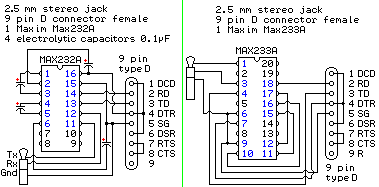
Most of the circuits I've found use the MAX232(/A) or MAX233(/A) chip, like this particularly well-drawn schematic I found on the Casiopeia Forums:
This design uses a combination of the MC14C88 and MC14C89 line drivers:
Note: Like the other drawings here, this was found wading through Google Image Search results, but its containing page returns a 403
I have no idea how the 74HC14 "Inverting Hex Schmitt Trigger" is helpful but apparently this is another way it can be done:

Someone else used a 74LS14 (same difference, right?).
I also found the original patented Casio-commissioned (I think?) link cable, but besides the fact that
...if you make one ... more for your education than saving money, ... technically you would be infringing the patent, [but] it is impossible for anyone to stop you.
I don't want to build that one becauseYou can put the PCB inside the DB9 but you'll need to pull up R[5?] to avoid cable coupling but the pull-up will draw current form the Casio which defeats a very important feature of the circuit and will cost you a lot replacing batteries.
The winner?
I find this anonymous design posted on old.pinouts.ru the most interesting, though. It uses a bunch of discrete components:
As far as I can see this design seems to suit my requirements the most:
- First of all, it doesn't require a dedicated power supply! ALL the chip-based configurations I've come across specify a 7805 in the design, and one of the MAX232 schematics I found incorporates a serial/9V battery switch, noting that not all serial ports are happy being power supplies. Besides an offtopic mini-rant about half of these designs being circa or beyond 1998 and the invention of (ta-da!) USB (although a power cable going to a USB port would be clunky too), the discrete-component-based circuit above doesn't say "insert 5V@500mA here" or similar anywhere so wins in my book.
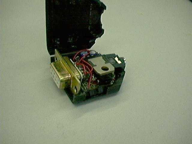
- I've done a rough "physical assembly" sketch of the schematic, and yes, there *are* three transistors, six diodes and six resistors to take into account, but I think I can *probably* cram the whole circuit into the serial plug itself, instead of sprawling it out on a giant PCB or proto/breadboard and requiring a giant project case (<-- eww).
The 74LS14-based design I mentioned above fits inside a serial plug...
...but it has three limitations:
- It uses a breadboard, and I want to avoid that technique if I can.
- It uses an IC and thus [has to] exploit[s] the 9V-harvesting technique, which as far as I understand won't work with all serial controllers.
- This design incorporates a 2.5mm socket and uses a pre-made/moulded 2.5mm plug-to-plug cable to do the connecting. Since I'm making link cables for both my TI and my Casio I'll be using different serial- and 2.5mm plug models and different cable colors so I can tell them apart (!), so the cable must not be removeable so this can work. Thus, I need to be able to take advantage of the strain-relief bracket that will come with the plug, and I'll subsequently have less room to work with.
I'd appreciate the feedback and advice of both the geometrically and electronically minded in deciding what I should do here (one can always tell a problem is complicated when it requires a nested HTML list to format/explain it
 ).
).To sum up:
- I'd like to know if anyone can see any electrical caveats in the design I've selected - in particular, will the circuit behave if I cram it into the plug, or will it misbehave like the patented one would?
- Has anyone to fit 15 components in a serial plug and found it impossible?

-i336_
PS. IP.Board mangled the case of my post - I titled it "CFX-9850GB+". Admin can hax non-sane default? :P


