Jump to content


Photo
- - - - -

Project:fx5800p Data Link


  • Please log in to reply
9 replies to this topic

#1 ECE

ECE

    Casio Freak

  • Members
  • PipPipPipPip
  • 152 posts
  • Gender:Not Telling
  • Location:USA

  • Calculators:
    ClassPad300 Plus o.s3.06.1000
    fx-CG20 o.s1.04
    fx9860GII SD o.s2.00
    fx9860G Slim o.s1.10
    fx9860GSD o.s2.01 (GII hacked)
    Algebra FX2.0 Plus
    CFX9850GBplus
    fx5800p
    fx3650p
    fx570ES Plus
    EA-200 Casio Data Analyzer

Posted 09 July 2011 - 11:18 PM

Hi,

This is an attempt to build a data link for the fx5800P to be able to transfer data and store it on a PC.

As a start I measured the voltage levels of thetransmitted signal from the 2.5mm jack. The levels where 0-2.7v, so to connect the calc to PC using a MAX232 based cable see this link http://www.casiocalc...=2686&hl=max232
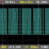
I needed a voltage level of 0-5V. Thus I constructeda simple level converter based on the LM339 comparator which was in my reach. Fig.1 shows the schematic of the level converter, Fig.2 and Fig.3 shows the transmittedsignal before and after the level converter. Fig.4 is the 2.5mm Jack.

Posted Image

Posted Image Posted Image Posted Image

The next step is to figure out the protocol that fx5800P use. I needed the baud rate, data bits, parity bits, stop bits to connect the calc to PC HyperTerminal or any other s/w to analyze the outgoing signals using COM port (RS232 serial port). Any suggestions?

Edited by M.Yasser, 09 July 2011 - 11:52 PM.


#2 ECE

ECE

    Casio Freak

  • Members
  • PipPipPipPip
  • 152 posts
  • Gender:Not Telling
  • Location:USA

  • Calculators:
    ClassPad300 Plus o.s3.06.1000
    fx-CG20 o.s1.04
    fx9860GII SD o.s2.00
    fx9860G Slim o.s1.10
    fx9860GSD o.s2.01 (GII hacked)
    Algebra FX2.0 Plus
    CFX9850GBplus
    fx5800p
    fx3650p
    fx570ES Plus
    EA-200 Casio Data Analyzer

Posted 10 July 2011 - 11:36 AM

An attempt to find the baud rate, I connected the scope to the tip of the 2.5mm jack and issue a transmit command for a selected data in the calc memory. I repeated this action with the probe of the scope connected to the middle of the 2.5mm jack (I really don't know which one i.e. tip or middle is transmit or receive). Fig.1 below is for the first case, Fig.2 is for the second.

Posted Image Posted Image


I tried to measure the narrowest pulse width to make an estimate of the baud rate. Fig.1 dt=64 us (micro second), Fig.2 dt=160 us. Fig.1 seems like a strobe of uniform pulses (clock).

Ok, now i'll issue a receive command and see what happens.

No signal on the tip nor the middle, but when I press cancel (AC button), a signal shows. Fig.3 is for the Tip (2.5mm jack) and Fig.4 is for the middle (2.5mm jack).

Posted Image Posted Image


It seems that the tip is a clock to the data from the middle. Ok I have to make more measurements .

Edited by M.Yasser, 10 July 2011 - 12:09 PM.


#3 ECE

ECE

    Casio Freak

  • Members
  • PipPipPipPip
  • 152 posts
  • Gender:Not Telling
  • Location:USA

  • Calculators:
    ClassPad300 Plus o.s3.06.1000
    fx-CG20 o.s1.04
    fx9860GII SD o.s2.00
    fx9860G Slim o.s1.10
    fx9860GSD o.s2.01 (GII hacked)
    Algebra FX2.0 Plus
    CFX9850GBplus
    fx5800p
    fx3650p
    fx570ES Plus
    EA-200 Casio Data Analyzer

Posted 10 July 2011 - 03:14 PM

Posted Image

This is a 2 channel scope image, the yellow signal is fromthe Tip of the 2.5mm jack and the blue signal is from the middle (2.5mm Jack). Thesignals are recorded simultaneously after issuing a transmit command. It seems that the type of serial communication is Synchronous,(RS232 serial COM port in PC uses a different type of signal communicationcalled Asynchronous).

Refer to the figure above; the yellow signal is perhaps a clock strobe for the data signal in blue. Any suggestions?

Edited by M.Yasser, 10 July 2011 - 03:17 PM.


#4 ECE

ECE

    Casio Freak

  • Members
  • PipPipPipPip
  • 152 posts
  • Gender:Not Telling
  • Location:USA

  • Calculators:
    ClassPad300 Plus o.s3.06.1000
    fx-CG20 o.s1.04
    fx9860GII SD o.s2.00
    fx9860G Slim o.s1.10
    fx9860GSD o.s2.01 (GII hacked)
    Algebra FX2.0 Plus
    CFX9850GBplus
    fx5800p
    fx3650p
    fx570ES Plus
    EA-200 Casio Data Analyzer

Posted 11 July 2011 - 11:31 AM

Anyone interested?
A contribution may push the project forward.
Regards.

#5 djrose

djrose

    Newbie

  • Members
  • Pip
  • 12 posts

  • Calculators:
    Casio FX-9860G Slim, Casio AQ-1500, Personal Mini, CFX-9850G, SF-7100SY PLUS, FT-7, FX 2.0 PLUS, FX-3650P, FX5000-F, FX-730P, FX-7400, FX-8100, FX-850P, FX-991ES, MG-660, MG-775, MG-777, MG-80, MG-880, MG-90, ML-90, QD-700, SL-760, FX-4500P, FX-4000P, FX-115MS, FX-991MS, FX-6300G, QA-100, FX-83MS

    Hewlett Packard HP-49G+

    Radio Shack PC-2

    Sharp IQ-7000, IQ-8200, PC-1248, PC-1500, ZQ-700, ZQ-770P, EL-376S

    Texas Instruments TI-83, TI-89

    Kingson Mechanical Calculator

Posted 12 July 2011 - 07:07 AM

Anyone interested?
A contribution may push the project forward.
Regards.


Sorry, I've got too many other commitments and don't have the time to contribute.

However, I agree with your conclusion. It looks like clocked communications. Not uncommon.

Practically, if I were to interface a PC to these signals, I would consider using a separate processor. Hobbyists would probably go for a PIC. I'd prefer to go for something like an STM32. That could use a couple of port pins to directly interface with the calculator (with suitable protection) and either USB or asynchronous interface to talk to a PC. You can get pretty good development boards off ebay for under £15.

Would be an interesting little project and would really like to help - But don't think I can.

#6 ECE

ECE

    Casio Freak

  • Members
  • PipPipPipPip
  • 152 posts
  • Gender:Not Telling
  • Location:USA

  • Calculators:
    ClassPad300 Plus o.s3.06.1000
    fx-CG20 o.s1.04
    fx9860GII SD o.s2.00
    fx9860G Slim o.s1.10
    fx9860GSD o.s2.01 (GII hacked)
    Algebra FX2.0 Plus
    CFX9850GBplus
    fx5800p
    fx3650p
    fx570ES Plus
    EA-200 Casio Data Analyzer

Posted 12 July 2011 - 11:47 AM

Hi djrose, :)
I’ve already bought an EasyPic6 development board from MikroElektronika: http://www.mikroe.co...lopment-system/ .
The wave forms are similar to I2C signals. I haven’t worked before with I2C. Some PIC microcontrollers support I2C bus. I need something to analyze the calc signals to make a conclusion.
Regards.

#7 djrose

djrose

    Newbie

  • Members
  • Pip
  • 12 posts

  • Calculators:
    Casio FX-9860G Slim, Casio AQ-1500, Personal Mini, CFX-9850G, SF-7100SY PLUS, FT-7, FX 2.0 PLUS, FX-3650P, FX5000-F, FX-730P, FX-7400, FX-8100, FX-850P, FX-991ES, MG-660, MG-775, MG-777, MG-80, MG-880, MG-90, ML-90, QD-700, SL-760, FX-4500P, FX-4000P, FX-115MS, FX-991MS, FX-6300G, QA-100, FX-83MS

    Hewlett Packard HP-49G+

    Radio Shack PC-2

    Sharp IQ-7000, IQ-8200, PC-1248, PC-1500, ZQ-700, ZQ-770P, EL-376S

    Texas Instruments TI-83, TI-89

    Kingson Mechanical Calculator

Posted 12 July 2011 - 02:02 PM

Hi djrose, :)
I've already bought an EasyPic6 development board from MikroElektronika: http://www.mikroe.co...lopment-system/ .
The wave forms are similar to I2C signals. I haven't worked before with I2C. Some PIC microcontrollers support I2C bus. I need something to analyze the calc signals to make a conclusion.
Regards.


It could be I2C and it should be easy to determine - By looking for the stop and start conditions. This is where the data line changes state when the clock is in it's active state.

Regardless, with what you're scoping, it seems obvious that the calculator is the master - And when two are connected together, it would probably be the transmitter that is the master.

I'm not a gambler - But if I were, I'd bet on it being synchronous serial data.

I saw a post of yours on sonsivri (a great forum :) ).

I've recently got an FX-5800P. I have a few STM32 based boards, Keil development environment and a ULINK2 - What I don't have is the time. Your posts are making me think I'd like to look though.

#8 ECE

ECE

    Casio Freak

  • Members
  • PipPipPipPip
  • 152 posts
  • Gender:Not Telling
  • Location:USA

  • Calculators:
    ClassPad300 Plus o.s3.06.1000
    fx-CG20 o.s1.04
    fx9860GII SD o.s2.00
    fx9860G Slim o.s1.10
    fx9860GSD o.s2.01 (GII hacked)
    Algebra FX2.0 Plus
    CFX9850GBplus
    fx5800p
    fx3650p
    fx570ES Plus
    EA-200 Casio Data Analyzer

Posted 12 July 2011 - 06:20 PM

Hi,
I’ll try to get hands on another fx5800P and scope the signals while the two calcs communicate, maybe tomorrow.

I saw a post of yours on sonsivri (a great forum ) :).

Yes I’m trying to find a solution and maybe it will help someone else.

Your posts are making me think I'd like to look though.


I’m glad. :D

Edited by M.Yasser, 12 July 2011 - 06:22 PM.


#9 ECE

ECE

    Casio Freak

  • Members
  • PipPipPipPip
  • 152 posts
  • Gender:Not Telling
  • Location:USA

  • Calculators:
    ClassPad300 Plus o.s3.06.1000
    fx-CG20 o.s1.04
    fx9860GII SD o.s2.00
    fx9860G Slim o.s1.10
    fx9860GSD o.s2.01 (GII hacked)
    Algebra FX2.0 Plus
    CFX9850GBplus
    fx5800p
    fx3650p
    fx570ES Plus
    EA-200 Casio Data Analyzer

Posted 21 July 2011 - 02:03 PM

Hi,

Below are scope images of two calculators; one of them is sending data to the other one.

The left column images are for the Tip of the 2.5mm jack with respect to the sender and the right column images are for the Middle of the 2.5mm jack. Each row represents the same instant of time.

Posted Image Posted Image

Posted Image Posted Image

Posted Image Posted Image

Posted Image Posted Image

Posted Image Posted Image

#10 ECE

ECE

    Casio Freak

  • Members
  • PipPipPipPip
  • 152 posts
  • Gender:Not Telling
  • Location:USA

  • Calculators:
    ClassPad300 Plus o.s3.06.1000
    fx-CG20 o.s1.04
    fx9860GII SD o.s2.00
    fx9860G Slim o.s1.10
    fx9860GSD o.s2.01 (GII hacked)
    Algebra FX2.0 Plus
    CFX9850GBplus
    fx5800p
    fx3650p
    fx570ES Plus
    EA-200 Casio Data Analyzer

Posted 21 July 2011 - 02:08 PM

Posted Image Posted Image

Posted Image Posted Image

Posted Image Posted Image

Posted Image Posted Image
Now, can anybody suggest a method to analyze the data (scopeimages are hard to track?).

Regards.


0 user(s) are reading this topic

0 members, 0 guests, 0 anonymous users